 English
 Español
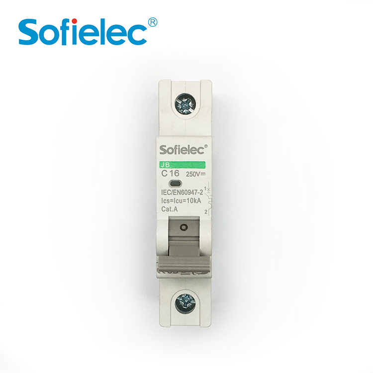
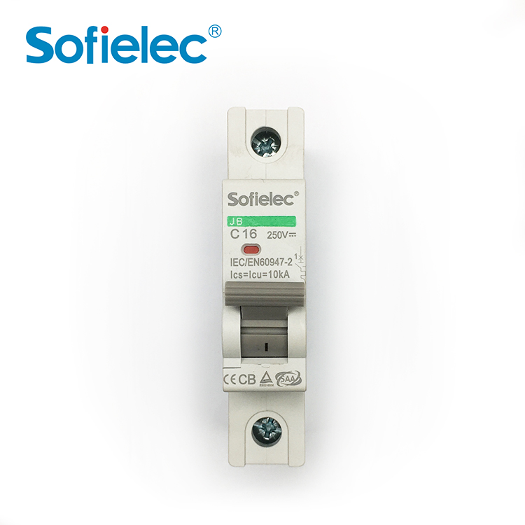
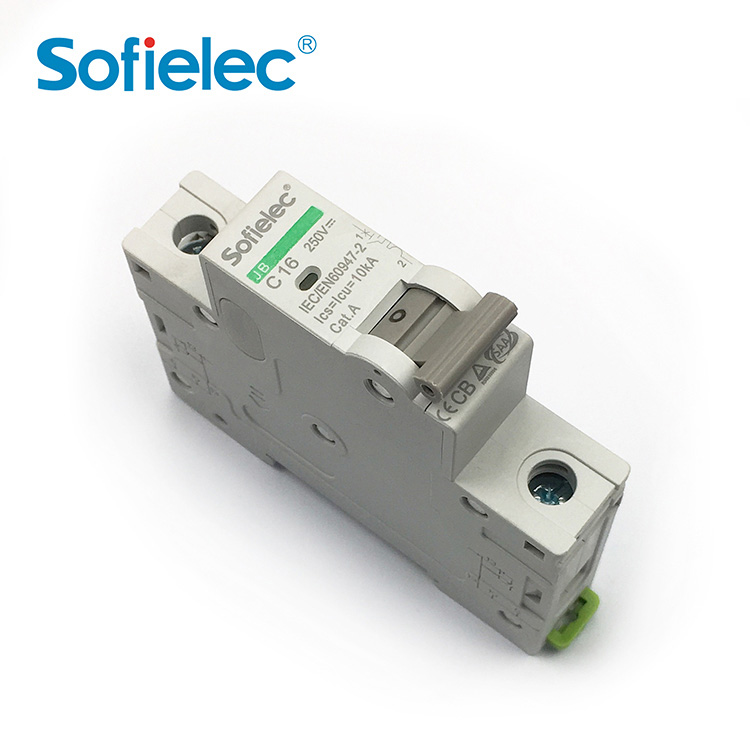
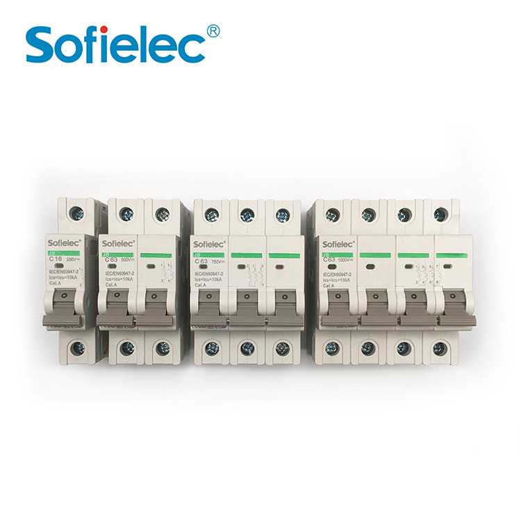
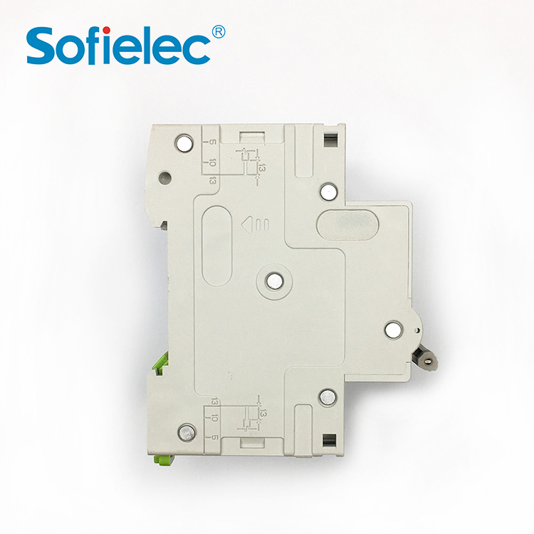
| Categories | DC Series |
| Model | JB Type |
| Rated insulation voltage | 1000V DC |
| Breaking capacity | 10kA |
| Impluse voltage | 4kV |
| Electrical connection | By the bottom for In and Out |
| Number of poles | 1P 2P 3P 4P |
| Rated service breaking capacity | 100 % of the Icu |
| Mechanical | 20,000 cycles |
| Degree of pollution | 2 |
| Category | A (no delay in accordance with IEC / EN 60947-2 st |
| Tropicalisation | Relative humidity: 95 % at 55°C in accordance with |
| Terms of Payment | L/C, Western Union, MoneyGram, T/T, Paypal |
Construction and Feature
The JB is a DC circuit breaker dedicated to multi string photovoltaic installations. This circuit breaker is designed to protect the cables located between each string of photovoltaic modules and the photovoltaic inverter against overloads and short circuits (see application diagram).
Combined with a switch , the JB will be installed in a string PV protection enclosure at the end of each string of photovoltaic modules.
It can be locked (by a padlocking device) in OFF position as a safety measure for removal of the PV inverter.
Since a fault current can flow in the reverse direction to the operating current, the JB can detect and protect against any bidirectional current.
To ensure the safety of the installation, it is necessary, depending on the various types of application, to combine the JB with:
■ a residual current device at the AC end,
■ a fault passage detector (insulation monitoring device) at the DC end
■ an earth protection circuit breaker at the DC end
In all cases, fast action on site will be required to clear the fault (protection not ensured in the event of a double fault).
JB is not polanity sensitive: (+) and (-) wires can inversed without any risk.
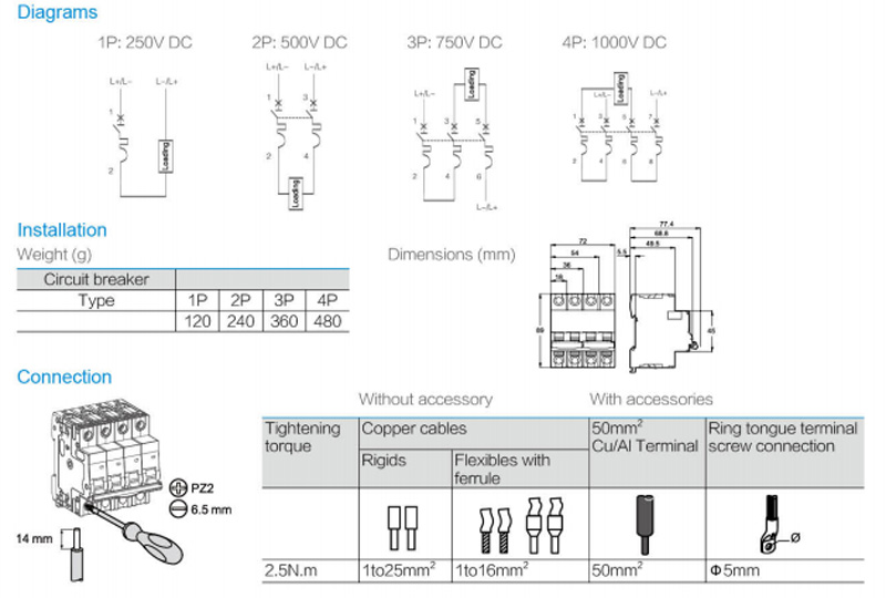
The JB is: delivered with three inter-pole barrier to provide increased isolation distance between two adjacent connectors.
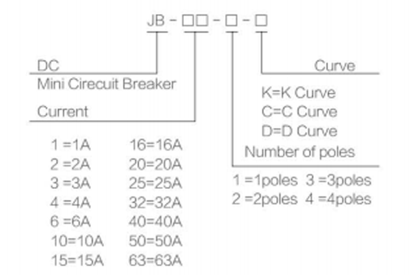
Meaning and classification models
Main characteristics
| Operating voltage (Ue) |
1P=250V DC,2P=500V DC 3P=750 V DC, 4P=1000V DC |
| Rated insulation voltage(Ui) | 1 ,000V DC |
| Breaking capacity (Icu) | 10kA |
| Impulse voltage (Uimp) | 4kV |
| Electrical connection | By the botom for In and Out |
| Number of poles | 1P, 2P, 3P, 4P |
| Standards |
IEC 60947-2 EN 60947-2 |
Characteristic Curve
■ Position contact indication - suitabilty for isolation according to IEC/EN 60947-2 standard.
■ The presence of the green strip guarantees physical opening of the contacts and allows operations to be performed on the downstream circuit in complete safety.
■ Increased product service life thanks to fast closing independent of the speed of actuation of the toggle.
■Pre -wired product: Input / Output on the same side.
Power Coumption
| Rated service breaking capacity (lcs) | 100% of the lcu | |
| Endurance(O-C) | Electrical | 1,500 cycles(whern L/R=2 ms) |
| Mechanical | 20,000 cycles | |
| Mechanical | 20,000 cycles | |
| Degreen of pollution | 2 | |
| Category | A (no delay in accordance with IEC1 EN 60947-2 standards) | |
|
Degree of protection Device in modular (IEC 60529) enclosure |
IP40 | |
| Tropicalisation | Relative humidity: 95 % at 55C in accordance with IEC 60068-2 and GB 14048.2 standards | |
| Temperature | Operating | -25℃ to70 ℃ |
| Storage | -40℃ to 85℃ | |
> Is an SPD Surge Protective Device Rated for 80kA Imax?
An SPD Surge Protective Device with 5-80kA discharge capacity, built-in disconnector, and visual status window — built for low-voltage distribution system protection...
> Does a Float Switch Need IP68 for Hot Water?
A Float Switch with IP68 sealing, AC 220V rating, and 60°C water temperature tolerance — built for reliable liquid level control in pumps and tanks.
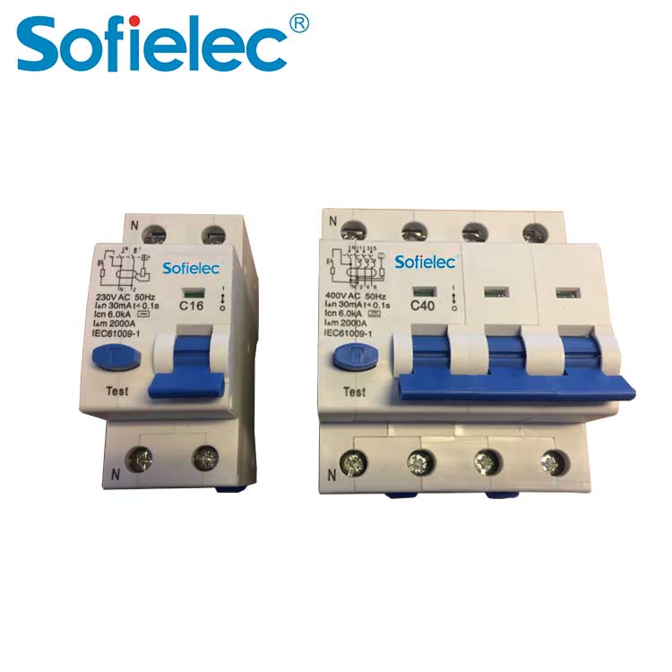
> Does a Circuit Breaker Need Both Overcurrent and Leakage Protection?
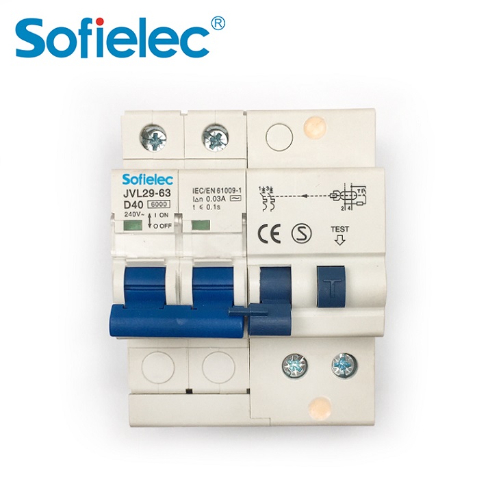
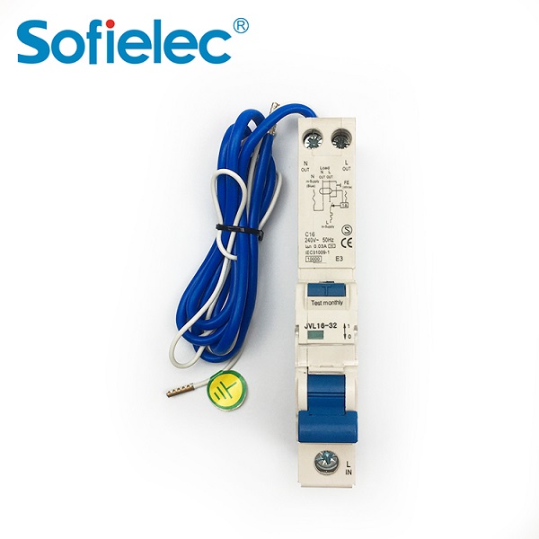
A magnetic RCBO that combines overcurrent and earth leakage protection in a compact two-module design — featuring 10kA breaking capacity and CE approval for resident...
> What Makes the ASFT Series Outperform Other Float Switches?
A float switch with integrated square-axis multi-pole design, welding-process contacts with silver solder pads, and bite-process terminal blocks — built for reliable...