| Categories | Economic 4.5KA, 6kA Regular Series Circuit Breaker |
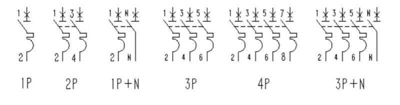
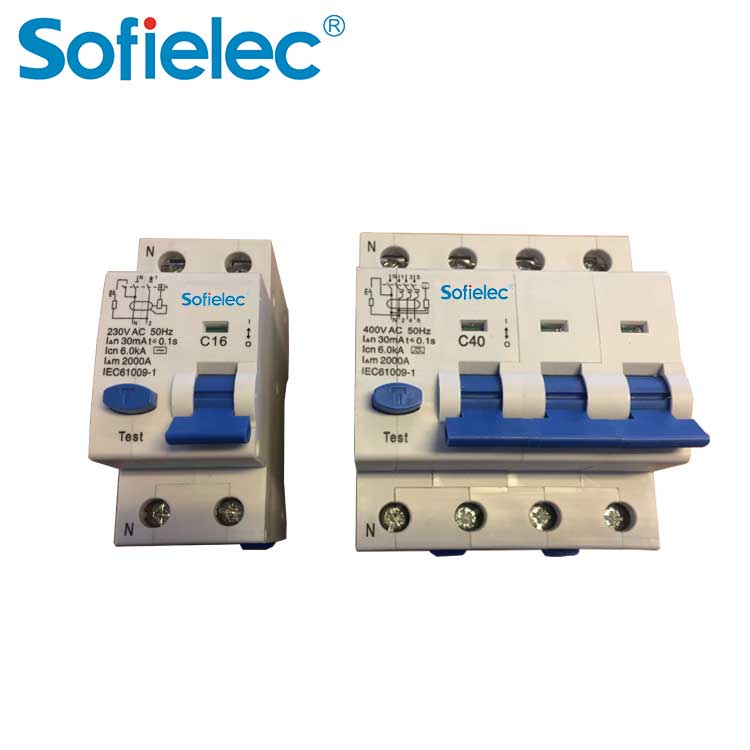
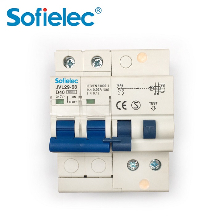
| Pole No | 1P. 1P+N. 2P. 3P. 3P+N. 4P |
| Rated current(A) | 1. 2. 3.4. 6. 10.16. 20. 25. 32. 40. 50. 63 |
| Rated voltage | AC 230. 230/400. 400 |
| Rated Frequency | 50/60Hz |
| Tripping curve | B. C. D |
| Rated short-circuit capacity (Icn) | 6000A |
| Mechanical life | 20000 times |
| Contact position | indication window |
| Degree of protection | IP20 |
| Connection terminal | Pillar terminal with clamp |
Construction and Feature
■ Fine and unique
appearance,advanced
design
■ Short-circuit and overload
dual-protection performance
■ High-breaking capacity
(6KA) that is leading among
the world similar products
■ Mechanical life:4000 times
■ Convenient and reliable
installation
Technical Data
|
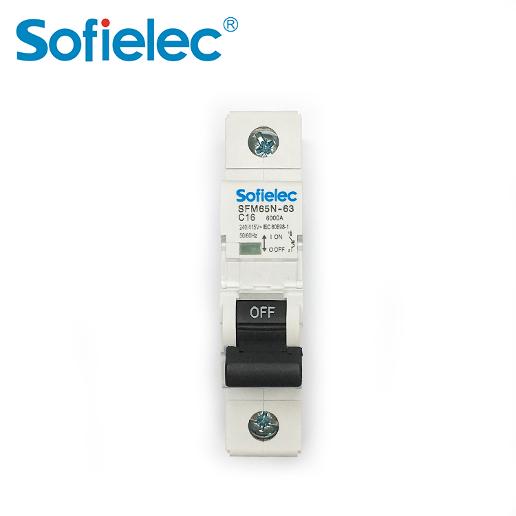
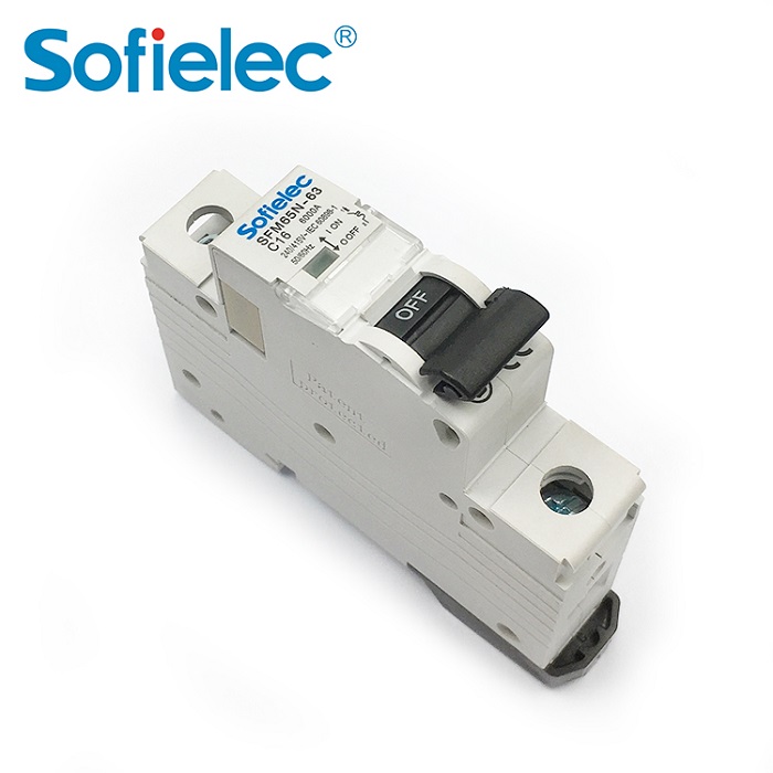
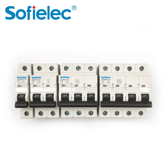
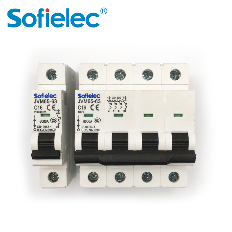
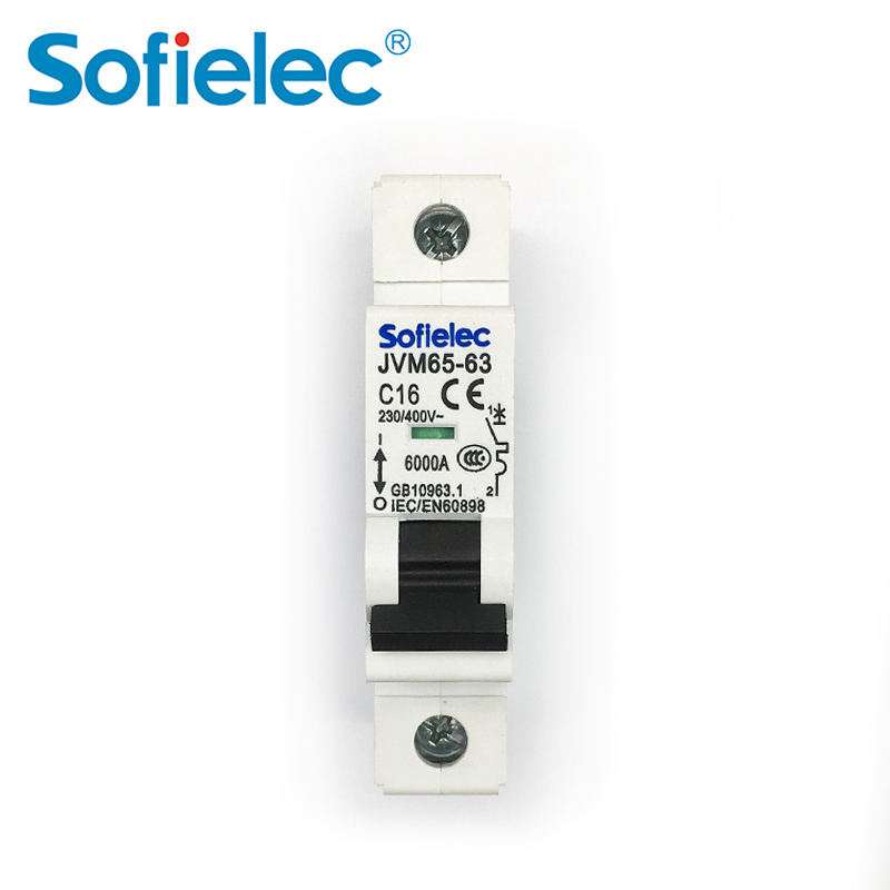
■ Model: SFM65-63 |
|
■ Pole No.: 1P, 1P+N, 2P, 3P. 3P+N, 4P |
|
■ Rated current(A):1、2、3、4、6、10、16、20、25、32、40、50、63 |
|
■ Rated voltage: AC 230, 230/400. 400 |
|
■ Rated Frequency: 50/60HZ |
|
■ Tripping curve: B, C. D |
|
■ Rated short-circuit capacity (Icn) :6000A |
|
■ Mechanical life: 20000 times |
|
■ Contact position indication window |
|
■ Degree of protection: IP20 |
|
■ Connection terminahPillar terminal with clamp |
|
■ Connection conductor: up to and including 16mm |
|
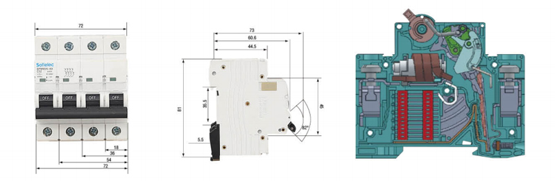
■ Terminal Connection Height:H1=19.5mm,H2=21.5mm |
|
■ lnstallation:DIN-rail mounting |
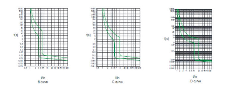
Characteristic Curve
Power Conumtion
| Rated current range(InA) | Max consumption/pole(W) |
| In<10 | 3 |
| 10 | 3.5 |
| 16 | 4.5 |
| 25 | 6 |
| 32 | 7.5 |
| 40 | 9 |
| 50 | 13 |
Wiring Diagram
Overload Current Protection Characteristics
| Test Procedure | Type | Test Current | Initial State | Tripping or Non-tripping Time Limit | Expected Result | Remark |
| a | B,C,D | 1.13In | cold | t≤1h | no trippint | |
| b | B,C,D | 1.45In | After test a | t<1h | tripping |
Current in the 5 s in the increase of stability |
| c | B,C,D | 2.55In | cold |
1s60s(In≤32A) 1s32A) |
tripping | |
| d | B | 3In | cold | t≤0.1s | no tripping |
Turn on the auxiliary switch to close the current |
| C | 5In | cold | ||||
| D | 10In | cold | ||||
| e | B | 5In | cold | t<0.1s | tripping |
Turn on the auxiliary switch to close the current |
| C | 10In | cold | ||||
| D | 20In | cold |
Overall&installation Dimensions
> How to Diagnose a Failing Surge Protective Device (SPD) – Step‑by‑Step Troubleshooting
SPD failed without visible damage? Learn to check status indicators, measure leakage current, and know when to replace.
> What Is a Timer Relay?
What’s the difference between on‑delay and off‑delay? Can a timer relay replace a PLC? Answers to 6 common B2B questions.
> Common Causes of Overload Relay Tripping and How to Prevent Them
Why does your motor overload relay keep tripping? Learn real causes (overload, phase loss, ambient heat) and how to prevent false trips.
> Application Guide for Hydraulic Magnetic Circuit Breakers in Sensitive Electronic Equipment
Why use hydraulic magnetic breakers for medical, IT or telecom equipment? Temperature stability, delay curves, and selection tips.