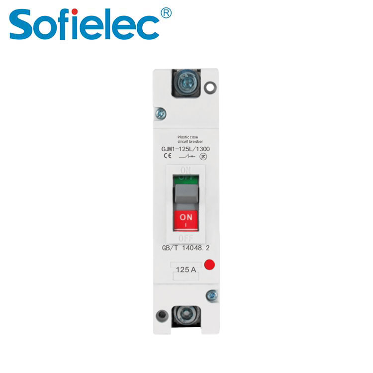
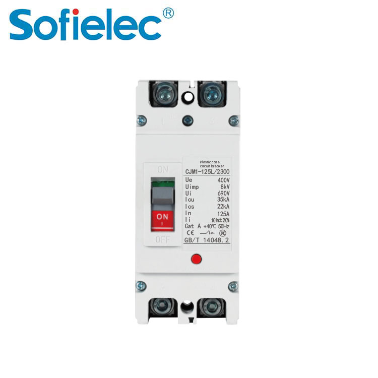
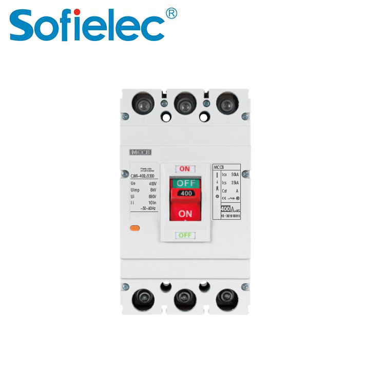
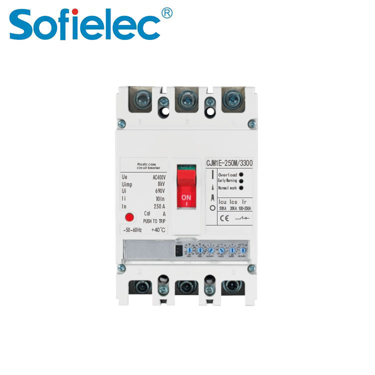
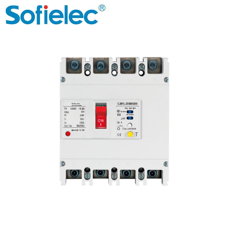
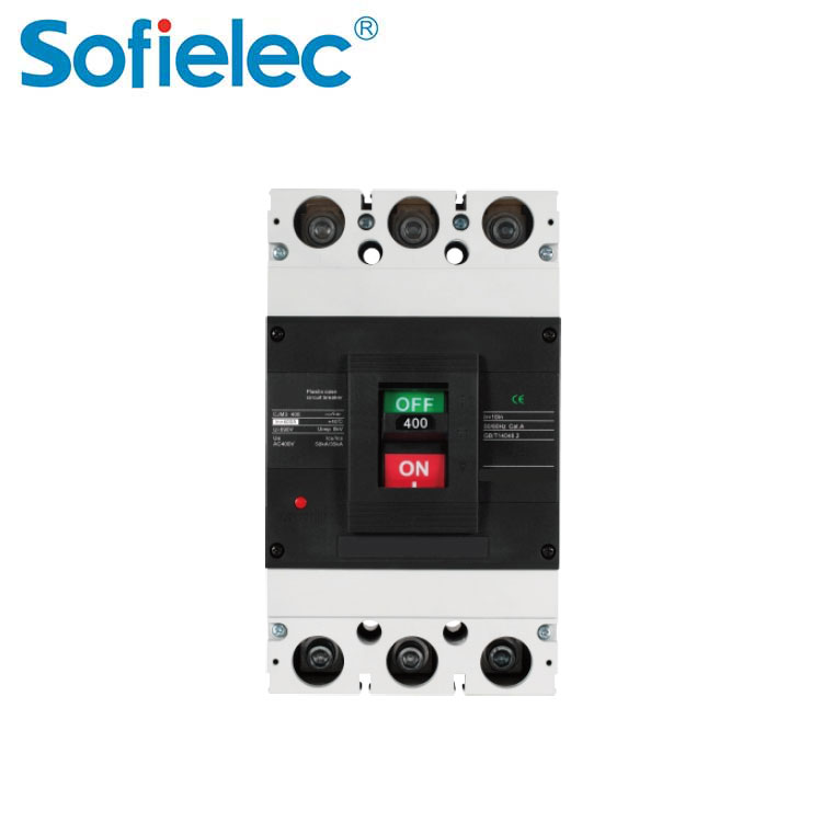
CJMM1 Series Moulded Case Circuit Breakers Application
CJMM1 series moulded case circuit breaker(hereinafter referred to as circuit breaker) is pplicable for AC 50/60HZ power distribution network circuit with rated insulation voltage of 800V, rated operation voltage of 690V and rated operation current from 10A to 630A, it's used to distribute power and prevent circuit and power supply equipment from damage due to overload, short circuit, under voltage and other faults, it's also used for infrequent start of motor as well as overload, short circuit and under volt-age protection
This circuit breaker owns advantages of small volume, high breaking capacity, short arcing (or noarcing)etc, it can be equipped with access-ories like alarm contact, shunt release, auxiliary contact etc, it's an ideal product for user.
The residual current circuit breaker can either be vertically installed (vertical installation) or be horizontally installed (horizontal installation)
The product is in accordance with the standards of IEC60947-2 and Gb140482
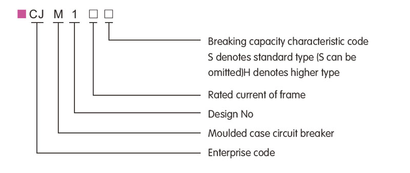
CJMM1 Series AC MCCB Product model
Note: There are four types of neutral pole (N pole) for four phases product.
The neutral pole of type A is not equipped with over-current tripping element, its always switched on, and it is not switched on or off together with other three poles.
The neutral pole of type B is not equipped with over-current tripping element, and it's switched on or off together with other three poles(the neutral pole is switched on before being switched off)
The neutral pole of type C is equipped with over-current tripping element, and it's switched on or off together with other three poles(the neutral pole is switched on before being switched off)
The neutral pole of type D is equipped with over-current tripping element, it's always switched on and is not switched on or off together with other three poles.
Moulded Case Circuit Breakers 800V MCCB Table 1
| Accessory name | Electronic release | Compound release |
| Auxiliary contact,under voltage release,alam contact | 287 | 378 |
| Two auxiliary contact sets, alarm contact | 268 | 368 |
| Shunt release, alarm contact, auxiliary contact | 238 | 348 |
| Under voltage release, alarm contact | 248 | 338 |
| Auxiliary contact alarm contact | 228 | 328 |
| Shunt release alarm contact | 218 | 318 |
| Auxiliary contact under-voltage release | 270 | 370 |
| Two auxiliary contact sets | 260 | 360 |
| Shunt release under-voltage release | 250 | 350 |
| Shunt release auxiliary contact | 240 | 340 |
| Under-voltage release | 230 | 330 |
| Auxiliary contact | 220 | 320 |
| Shunt release | 210 | 310 |
| Alarm contact | 208 | 308 |
| No accessory | 200 | 300 |
630A MCCB Classification
By breaking capacity: a standard type(type S) b higher breaking capacity type(type H)
By connection mode: a front board connection, b back board connection, c plugin type
By operation mode: a direct handle operation, b rotation handle opera-tion,c electrical operation
By number of poles: 2P, 3P, and 4P
By accessory: alarm contact, auxiliary contact, shunt release, under voltage release.
MCCB Normal Service Condition
■ The altitude of the installation site shall not exceed 2000m
■ Ambient air temperature
□ The ambient air temperature shall not exceed +40℃
□ The average value shall not exceed +35℃ with in 24 hours
□ The ambient air temperature shall not be less than-5℃
■ Atmosphere condition
There lative humidity of atmosp here shall not exceed 50% at highest temperature of +40℃,and it can be higher atalower temperature,when theaver agelowest temp-erature in the wettest month doesn't exceed 25℃ can be 90%,conden sationon product surfacedue to temperature change must be takenin to account.
CJMM1 Series Moulded Case Circuit Breakers (MCCB) Main Technical Parameter
1 Rated value of circuit breakers
| Model | Imax (A) |
Specifications (A) |
Rated Operation Voltage (V) |
Rated Insulation Voltage (V) |
Icu (kA) |
Ics (kA) |
Number of Poles (P) |
Arcing Distance (mm) |
| CJMM1-63S | 63 | 6,10,16,20 25,32,40, 50,63 |
400 | 500 | 10* | 5* | 3 | 3 3,4 |
| CJMM1-63H | 63 | 400 | 500 | 15* | 10* | 3,4 | ||
| CJMM1-100S | 100 | 16,20,25,32 40,50,63, 80,100 |
690 | 800 | 35/10 | 22/5 | 3 | 3 2,3,4 |
| CJMM1-100H | 100 | 400 | 800 | 50 | 35 | 2,3,4 | ||
| CJMM1-225S | 225 | 100,125, 160,180, 200,225 |
690 | 800 | 35/10 | 25/5 | 3 | 3 2,3,4 |
| CJMM1-225H | 225 | 400 | 800 | 50 | 35 | 2,3,4 | ||
| CJMM1-400S | 400 | 225,250, 315,350, 400 |
690 | 800 | 50/15 | 35/8 | 3,4 | 3,4 3 |
| CJMM1-400H | 400 | 400 | 800 | 65 | 35 | 3 | ||
| CJMM1-630S | 630 | 400,500, 630 |
690 | 800 | 50/15 | 35/8 | 3,4 | 3,4 3 |
| CJMM1-630H | 630 | 400 | 800 | 65 | 45 | 3 |
Note: When the test parameters for the 400V, 6A without heating release
2 Inverse time breaking operation characteristic when each pole of overcurrent release for power distribution is powered on at the same time
| Item of test Current (I/In) | Test time area | Initial state |
| Non-tripping current 1.05In | 2h(n>63A),1h(n<63A) | Cold state |
| Tripping current 1.3In | 2h(n>63A),1h(n<63A) | Proceed immediately after No.1 test |
3 Inverse time breaking operation characteristic when each pole of overcurrent release for motor protection is powered on at the same time.
| Setting Current Conventional time Initial State | Note | ||
| 1.0In | >2h | Cold State | |
| 1.2In | ≤2h | Proceeded immediately after the No.1 test | |
| 1.5In | ≤4min | Cold State | 10≤In≤225 |
| ≤8min | Cold State | 225≤In≤630 | |
| 7.2In | 4s≤T≤10s | Cold State | 10≤In≤225 |
| 6s≤T≤20s | Cold State | 225≤In≤630 | |
4 The instantaneous operation characteristic of circuit breaker for power dis-tribution shall be set as 10in+20%, and the one of circuit breaker for motor protection shall be set as12ln±20%
Outline Installation Size
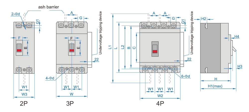
CJMM1-63,100,225,Outline and Installation Sizes (Front board connection)
| Sizes (mm) |
Model Code | ||||||
| CJMM1-63S | CJMM1-63H | CJMM1-63S | CJMM1-100S | CJMM1-100H | CJMM1-225S | CJMM1-225 | |
| Outline Sizes | C | 85 | 85 | 88 | 88 | 102 | 102 |
| E | 50 | 50 | 51 | 51 | 60 | 52 | |
| F | 23 | 23 | 23 | 22.5 | 25 | 23.5 | |
| G | 14 | 14 | 17.5 | 17.5 | 17 | 17 | |
| G1 | 6.5 | 6.5 | 6.5 | 6.5 | 11.5 | 11.5 | |
| H | 73 | 81 | 68 | 86 | 88 | 103 | |
| H1 | 90 | 98.5 | 86 | 104 | 110 | 127 | |
| H2 | 18.5 | 27 | 24 | 24 | 24 | 24 | |
| H3 | 4 | 4.5 | 4 | 4 | 4 | 4 | |
| H4 | 7 | 7 | 7 | 7 | 5 | 5 | |
| L | 135 | 135 | 150 | 150 | 165 | 165 | |
| L1 | 170 | 173 | 225 | 225 | 360 | 360 | |
| L2 | 117 | 117 | 136 | 136 | 144 | 144 | |
| W | 78 | 78 | 91 | 91 | 106 | 106 | |
| W1 | 25 | 25 | 30 | 30 | 35 | 35 | |
| W2 | - | 100 | - | 120 | - | 142 | |
| W3 | - | - | 65 | 65 | 75 | 75 | |
| Install Sizes | A | 25 | 25 | 30 | 30 | 35 | 35 |
| B | 117 | 117 | 128 | 128 | 125 | 125 | |
| od | 3.5 | 3.5 | 4.5 | 4.5 | 5.5 | 5.5 | |
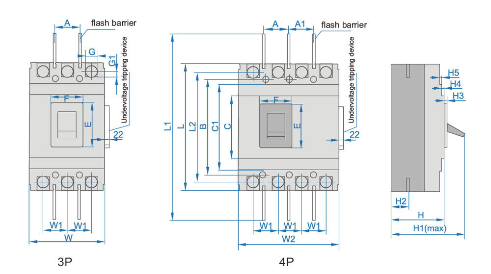
CJMM1-400,630,800,Outline and Installation Sizes (Front board connection)
| Sizes (mm) |
Model Code | ||
| CJMM1-400S | CJMM1-630S | ||
| Outline Sizes | C | 127 | 134 |
| C1 | 173 | 184 | |
| E | 89 | 89 | |
| F | 65 | 65 | |
| G | 26 | 29 | |
| G1 | 13.5 | 14 | |
| H | 107 | 111 | |
| H1 | 150 | 162 | |
| H2 | 39 | 44 | |
| H3 | 6 | 6.5 | |
| H4 | 5 | 7.5 | |
| H5 | 4.5 | 4.5 | |
| L | 257 | 271 | |
| L1 | 465 | 475 | |
| L2 | 225 | 234 | |
| W | 150 | 183 | |
| W1 | 48 | 58 | |
| W2 | 198 | 240 | |
| A | 44 | 58 | |
| Install Sizes | A1 | 48 | 58 |
| B | 194 | 200 | |
| Od | 8 | 7 | |
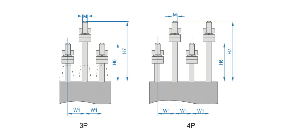
CJMMM1-63,100,225 Outline and installation size(back board connection)
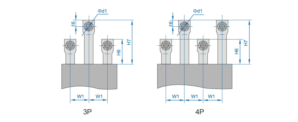
CJMM1-400,630 Outline and installation size(back board connection)
Outline Installation Size
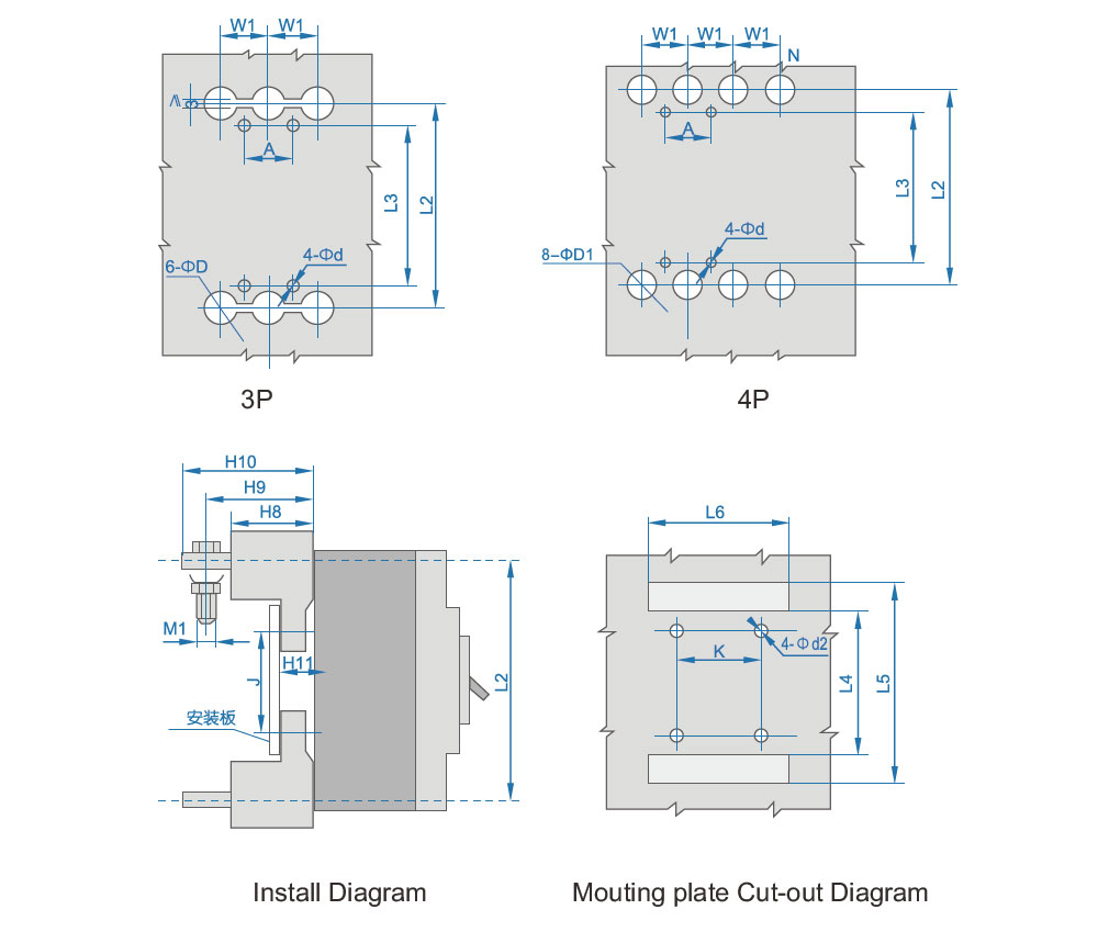
Back Board Connection Cut-out Diagram Plug In
| Sizes (mm) |
Model Code | ||||||
| CJMM1-63S CJMM1-63H |
CJMM1-100S CJMM1-100H |
CJMM1-225S CJMM1-225H |
CJMM1-400S | CJMM1-400H | CJMM1-630S CJMM1-630H |
||
| Sizes of Back Board Connection Plug in Type |
A | 25 | 30 | 35 | 44 | 44 | 58 |
| od | 3.5 | 4.5*6 deep hole | 3.3 | 7 | 7 | 7 | |
| od1 | - | - | - | 12.5 | 12.5 | 16.5 | |
| od2 | 6 | 8 | 8 | 8.5 | 9 | 8.5 | |
| oD | 8 | 24 | 26 | 31 | 33 | 37 | |
| oD1 | 8 | 16 | 20 | 33 | 37 | 37 | |
| H6 | 44 | 68 | 66 | 60 | 65 | 65 | |
| H7 | 66 | 108 | 110 | 120 | 120 | 125 | |
| H8 | 28 | 51 | 51 | 61 | 60 | 60 | |
| H9 | 38 | 65.5 | 72 | - | 83.5 | 93 | |
| H10 | 44 | 78 | 91 | 99 | 106.5 | 112 | |
| H11 | 8.5 | 17.5 | 17.5 | 22 | 21 | 21 | |
| L2 | 117 | 136 | 144 | 225 | 225 | 234 | |
| L3 | 117 | 108 | 124 | 194 | 194 | 200 | |
| L4 | 97 | 95 | 9 | 165 | 163 | 165 | |
| L5 | 138 | 180 | 190 | 285 | 285 | 302 | |
| L6 | 80 | 95 | 110 | 145 | 155 | 185 | |
| M | M6 | M8 | M10 | - | - | - | |
| K | 50.2 | 60 | 70 | 60 | 60 | 100 | |
| J | 60.7 | 62 | 54 | 129 | 129 | 123 | |
| M1 | M5 | M8 | M8 | M10 | M10 | M12 | |
| W1 | 25 | 35 | 35 | 44 | 44 | 58 | |
> How to Diagnose a Failing Surge Protective Device (SPD) – Step‑by‑Step Troubleshooting
SPD failed without visible damage? Learn to check status indicators, measure leakage current, and know when to replace.
> What Is a Timer Relay?
What’s the difference between on‑delay and off‑delay? Can a timer relay replace a PLC? Answers to 6 common B2B questions.
> Common Causes of Overload Relay Tripping and How to Prevent Them
Why does your motor overload relay keep tripping? Learn real causes (overload, phase loss, ambient heat) and how to prevent false trips.
> Application Guide for Hydraulic Magnetic Circuit Breakers in Sensitive Electronic Equipment
Why use hydraulic magnetic breakers for medical, IT or telecom equipment? Temperature stability, delay curves, and selection tips.