What is a contactor
Introduction to Contactors
Contactors are divided into alternating current contactors (voltage AC) and direct current contactors (voltage DC), which are used in electric power, power distribution and power consumption occasions. In a broad sense, a contactor refers to an electrical appliance that uses a coil to flow through a current to generate a magnetic field to close the contacts in order to control the load in industrial electricity.
In electrical engineering, because it can quickly cut off the main circuit of AC and DC and can frequently connect and control the circuit with high current (up to 800A), it is often used in electric motors as control objects, and can also be used to control factory equipment. For electrical loads such as electric heaters, working mother machines and various power units, contactors can not only connect and cut off circuits, but also have low-voltage release protection. The contactor has a large control capacity, is suitable for frequent operation and long-distance control, and is one of the important components in the automatic control system. In industrial electrical, there are many types of contactors, and the working current ranges from 5A to 1000A, and their uses are quite extensive.
How the contactor works
The working principle of the contactor is: when the contactor coil is energized, the coil current will generate a magnetic field, and the generated magnetic field will make the static iron core generate electromagnetic attraction to attract the moving iron core, and drive the AC contactor point to move, the normally closed contact is disconnected, The normally open contact is closed, and the two are linked. When the coil is powered off, the electromagnetic suction force disappears, and the armature is released under the action of the release spring, so that the contacts are restored, the normally open contacts are disconnected, and the normally closed contacts are closed. The working principle of a DC contactor is somewhat similar to that of a temperature switch.
AC contactor wiring method
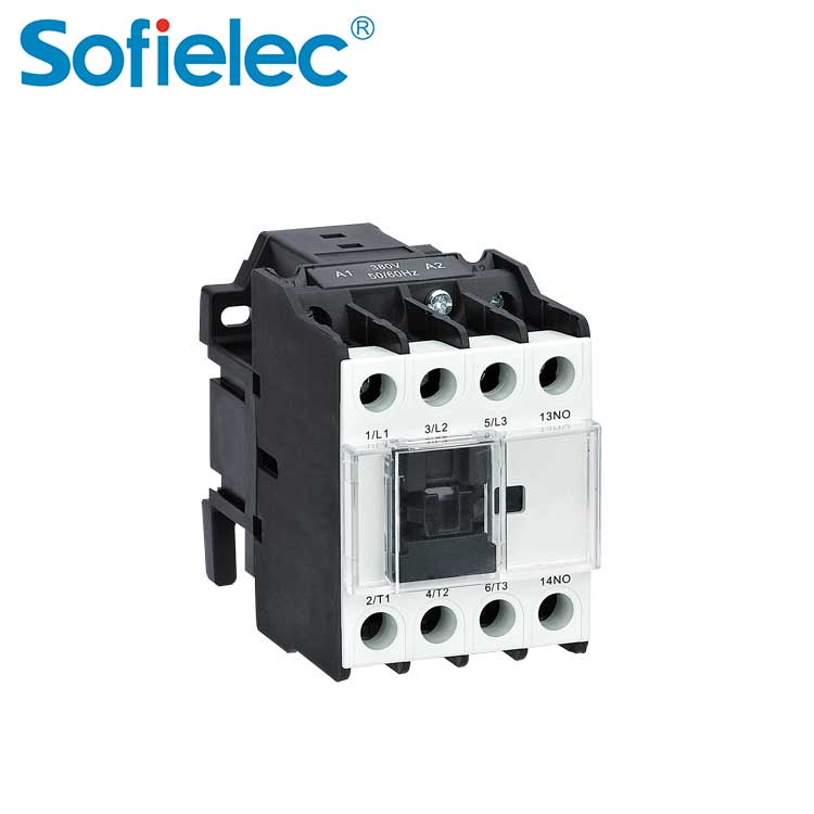
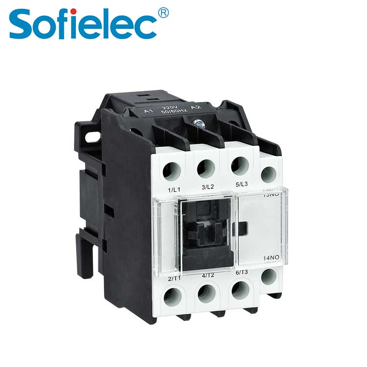
1, 3, 5 are connected to three-phase power supply, (main circuit part)
2, 4, 6 are connected to three-phase motors
A1 and A2 are the coils of the contactor, which are connected to the control circuit. By controlling the coils (A1, A2) of the contactor, the motor of the circuit part is controlled (small control large).
13, 14 represent the auxiliary contacts of the contactor, NO represents normally open, that is, 13, 14 are disconnected when there is no electricity, and 13, 14 are closed after electricity is turned on. It is placed in the control circuit part for self-locking (parallel to the start button) to achieve the purpose of continuous operation.
First, the three phases of the power supply are respectively connected to the main contacts L1, L2 and L3 of the contactor, and then three wires are connected from the T1, T2 and T3 of the contactor to the three terminals of the motor. The above is the main circuit.
Control circuit: lead a line from L1 to the stop button (the stop button is normally closed, the start button is normally open, you should know this!) From the stop button, connect one end of the start button and one end of the auxiliary contact of the contactor, Then connect the other end of the auxiliary contact from the other end of the start button (this part is also self-locking), the wire from this end is connected to coil A1, and the outlet of coil A2 is connected to L2 or L3.