16 knowledge points let you thoroughly understand the working principle and function of the RCCB/ELCB
1. What is a RCCB/ELCB?
Answer: The RCCB/ELCB (leakage protection switch) is an electrical safety device. Install the RCCB/ELCB in the low-voltage circuit. When leakage or electric shock occurs and reach the operating current value defined by the protector, it will immediately act within a limited time and automatically disconnect the power supply for protection.
2. What is the structure of the RCCB/ELCB?
Answer: The RCCB/ELCB is mainly composed of three parts: the detection element, the intermediate amplification link, and the operation actuator. ① Detection components. It is composed of zero-sequence transformer, which detects leakage current and sends out signals. ②Amplification link. Amplify the weak leakage signal according to different devices (the amplifying parts can be mechanical devices or electronic devices) to form an electromagnetic protector or an electronic protector. ③Executive agency. After receiving the signal, the main switch is switched from the closed position to the open position, thereby cutting off the power supply. It is a trip component that disconnects the protected circuit from the power grid.
3. What is the working principle of the RCCB/ELCB
Answer: ① When electrical equipment leaks, there are two abnormal phenomena:
One is that the balance of the three-phase current is disrupted and zero sequence current appears;
The second is that the non-charged metal shell has a voltage to the ground under normal conditions (under normal conditions, the metal shell and the earth are at zero potential).
②The role of zero-sequence current transformer The RCCB/ELCB obtains the abnormal signal through the current transformer detection, and transfers it through the intermediate mechanism, so that the actuator operates, and the power supply is disconnected through the switch device. The structure of a current transformer is similar to that of a transformer. It is composed of two coils that are insulated from each other and wound on the same core. When the primary coil has residual current, the secondary coil will induce current.
③The working principle of the RCCB/ELCB is to install the RCCB/ELCB in the circuit, the primary coil is connected with the circuit of the power grid, and the secondary coil is connected with the trip unit in the RCCB/ELCB. When the electrical equipment is operating normally, the current in the line is in a balanced state, and the sum of the current vectors in the transformer is zero (the current is a directional vector, for example, the direction of flow is "+", and the direction of return is "-". The currents going back and forth in the transformer are equal in magnitude, opposite in direction, and positive and negative cancel each other). Since there is no residual current in the primary coil, the secondary coil will not be induced, and the switch device of the RCCB/ELCB will operate in a closed state. When the equipment shell leaks and someone touches it in time, it will shunt at the fault point. This leakage current will return to the neutral point of the transformer (without current transformer) through the human body, earth, and working ground, causing the transformer to flow in and out. The current is unbalanced (the sum of the current vectors is not zero), and the primary coil generates residual current. Therefore, the secondary coil is induced, and when the current value reaches the operating current value limited by the RCCB/ELCB, the automatic switch trips to cut off the power supply.
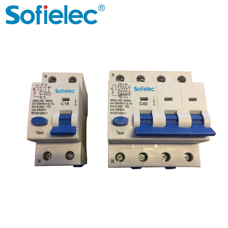
4. What are the main technical parameters of the RCCB/ELCB?
Answer: The main operating performance parameters are: rated leakage operating current, rated leakage operating time, and rated leakage non-operating current. Other parameters include: power frequency, rated voltage, rated current, etc. ①Rated leakage operating current The current value at which the RCCB/ELCB operates under specified conditions. For example, a 30mA protector, when the current value reaches 30mA, the protector will act to disconnect the power supply. ②The rated leakage operation time refers to the time from the sudden application of the rated leakage operation current to the time the protection circuit is cut off. For example, for a 30mA×0.1s protector, the time from the current value reaching 30mA to the separation of the main contact does not exceed 0.1s. ③Rated non-operating leakage current Under the specified conditions, the current value of the non-operating RCCB/ELCB should generally be one-half of the leakage operating current value. For example, a RCCB/ELCB with a leakage action current of 30mA, when the current value reaches 15mA or less, the protector should not operate, otherwise it may malfunction due to too high sensitivity and affect the normal operation of electrical equipment. ④Other parameters such as: power frequency, rated voltage, rated current, etc., when selecting a RCCB/ELCB, it should be compatible with the line and electrical equipment used. The working voltage of the RCCB/ELCB should adapt to the rated voltage of the normal fluctuation range of the power grid. If the fluctuation is too large, it will affect the normal operation of the protector, especially for electronic products. When the power supply voltage is lower than the rated working voltage of the protector, it will refuse to operate. The rated working current of the RCCB/ELCB should also be consistent with the actual current in the loop. If the actual working current is greater than the rated current of the protector, it will cause overload and cause the protector to malfunction.
5. What is the main protective function of the RCCB/ELCB?
Answer: The RCCB/ELCB mainly provides indirect contact protection. Under certain conditions, it can also be used as a supplementary protection for direct contact to protect against possible fatal electric shock accidents.
6. What is direct contact and indirect contact protection?
Answer: When the human body comes into contact with a charged body and current flows through the human body, it is called an electric shock. According to the cause of human body electric shock, it can be divided into direct contact electricity and indirect contact electricity. Direct electric shock refers to the electric shock caused by direct human contact with live objects (such as touching the phase line). Indirect contact electricity refers to the electric shock caused by the human body touching a metal conductor that is not charged under normal conditions and a charged metal conductor under fault conditions (such as touching the shell of a leakage device). According to the different causes of electric shock, the anti-shock measures taken for electric shock are also divided into: direct contact protection and indirect contact protection. Direct contact protection generally can use insulation, protective cover, fence, safety distance and other measures; indirect contact protection generally can use protective grounding (zero connection), protective cutoff, RCCB/ELCB and other measures.
7. What is the danger of electric shock to the human body?
Answer: When the human body gets an electric shock, the greater the current flowing into the human body, the longer the phase current lasts, the more dangerous it is. The degree of risk can be roughly divided into three stages: perception-get rid of-ventricular fibrillation. ① Perception stage. Since the current is very small, the human body can feel it (generally greater than 0.5mA), and it does not pose a hazard to people at this time; ②Get rid of phase. It refers to the maximum current value that a person can get rid of when an electrode is electrocuted (generally greater than 10mA). Although this current is dangerous, it can be rid of itself, so it basically does not constitute a fatal danger. When the current increases to a certain level, the person who gets an electric shock will contract the muscles and spasm, which will cause them to hold on to the charged body and cannot get rid of it by themselves. ③Ventricular fibrillation stage. As the current increases and the electric shock time is prolonged (generally greater than 50mA and ls), ventricular fibrillation will occur. If the power is not immediately disconnected, death will result. It can be seen that ventricular fibrillation is the most important cause of electrocution in the human body. Therefore, for human protection, it is often used not to cause ventricular fibrillation as the basis for determining the characteristics of electric shock protection.
8. What is the safety of "30mA·s"?
Answer: A large number of animal experiments and studies have shown that ventricular fibrillation is not only related to the current (I) passing through the human body, but also related to the duration of the current in the human body (t), that is, the safe electricity passing through the human body Q=I× t is determined, generally 50mA·s. That is to say, when the current is not more than 50mA and the current duration is within 1s, ventricular fibrillation generally does not occur. However, if it is controlled according to 50mA·s, when the power-on time is very short and the current is large (for example, 500mA×0.1s), there is still the risk of ventricular fibrillation. Although less than 50mA·s will not cause the consequences of electrocution, but it can also cause the person to lose consciousness or cause a secondary injury accident. Practice has proved that using 30 mA·s as the action characteristic of the electric shock protection device is more appropriate in terms of safety in use and manufacturing. Compared with 50 mA·s, it has a safety rate of 1.67 times (K=50/30). =1.67). It can be seen from the safety limit of "30mA·s" that even if the current reaches 100mA, as long as the RCCB/ELCB operates and cuts off the power supply within 0.3s, the human body will not cause a fatal danger. Therefore, the limit of 30mA·s has also become the basis for selection of RCCB/ELCB products.
9. Which electrical equipment needs to be installed with RCCB/ELCBs?
Answer: The "Technical Specification for Safety of Temporary Use of Electricity at Construction Sites" stipulates that "all electrical equipment on the construction site, except for protection and zero connection, must be equipped with a leakage protection device at the beginning of the equipment load line." The above provisions talk about three. Aspects: ① All electrical equipment on the construction site must be equipped with RCCB/ELCBs. Because of construction work in the open air, humid environment, changeable personnel, and weak equipment management links, electricity use is highly dangerous, requiring all electrical equipment including power and lighting equipment, mobile and fixed equipment, etc. Of course, it does not include equipment that uses safe voltage power supply and isolation transformer power supply. ② The original protective zeroing (grounding) measures carried out in accordance with regulations remain unchanged as required. This is the most basic technical measure for safe electricity use and cannot be removed. ③The RCCB/ELCB is installed at the head end of the load line of the electrical equipment. The purpose of this is to protect the electrical equipment while also protecting its load lines to prevent electric shock accidents caused by line insulation damage.
10. Why should a RCCB/ELCB be installed after the protection is connected to zero (grounding)?
Answer: Regardless of whether the protection is connected to zero or grounding, the protection range is always limited. For example, "protection connection to zero" is to connect the metal shell of electrical equipment with the neutral line of the power grid, and install a fuse on the power supply side. When electrical equipment encounters a shell failure (a certain phase touches the shell), a single-phase short circuit of the relatively neutral line is formed. Due to the large short-circuit current, the fuse is quickly blown and the power supply is disconnected for protection. Its working principle is to change the "shell-touch fault" to "single-phase short-circuit fault", so as to obtain large short-circuit current cut-off insurance. However, electrical shell bumping failures on the construction site are not frequent. Leakage faults often occur, such as leakage caused by equipment damp, excessive load, excessively long lines, and aging insulation. These leakage currents are small and cannot be quickly cut off. Therefore, the fault will not be automatically eliminated and will exist for a long time. But this kind of leakage current poses a serious threat to personal safety. Therefore, it is necessary to install a more sensitive RCCB/ELCB for supplementary protection.
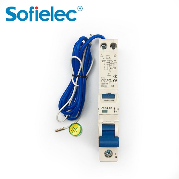
11.What are the types of RCCB/ELCBs?
Answer: The RCCB/ELCB is classified in different ways to meet the selection of use. For example, according to the action mode, it can be divided into voltage action type and current action type; according to the action mechanism, there are switch type and relay type; according to the number of poles and lines, there are unipolar two-wire, two-pole, two-pole three-wire and so on. The following is classified according to action sensitivity and action time: ①According to action sensitivity, it can be divided into: High sensitivity: Leakage action current is below 30mA; Medium sensitivity: 30~1000mA; Low sensitivity: above 1000mA. ②According to the action time, it can be divided into: fast type: leakage action time is less than 0.1s; delay type: action time is greater than 0.1s, between 0.1-2s; inverse time type: as the leakage current increases, the leakage action time decreases small. When the rated leakage operating current is used, the operating time is 0.2~1s; when the operating current is 1.4 times, it is 0.1, 0.5s; when the operating current is 4.4 times, it is less than 0.05s.
12.What is the difference between electronic and electromagnetic RCCB/ELCBs?
Answer: According to the different tripping methods, RCCB/ELCBs are divided into two types: electronic and electromagnetic: ①Electromagnetic trip type RCCB/ELCBs use electromagnetic trippers as the intermediate mechanism, and when leakage current occurs, the mechanism will trip and disconnect the power supply. . The disadvantages of this type of protector are: high cost and complex manufacturing process requirements. The advantages are: electromagnetic components have strong anti-interference and impact resistance (overcurrent and overvoltage impact); no auxiliary power supply is required; the leakage characteristics after zero voltage and phase failure remain unchanged. ②The electronic RCCB/ELCB uses a transistor amplifier as an intermediate mechanism. When a leakage occurs, it is amplified by the amplifier and transmitted to the relay, and the relay controls the switch to disconnect the power supply. The advantages of this kind of protector are: high sensitivity (up to 5mA); small setting error, simple manufacturing process and low cost. The disadvantages are: the transistor has a weak impact resistance and poor environmental interference resistance; it requires auxiliary working power (electronic amplifiers generally require more than ten volts of DC power), so that the leakage characteristics are affected by the fluctuation of the working voltage; when the main circuit lacks phase, the protector The protection function will be lost.
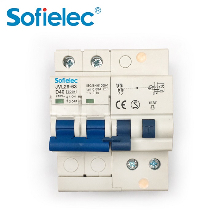
13.What are the protection functions of the leakage circuit breaker?
Answer: The RCCB/ELCB is mainly a device that provides protection when the electrical equipment has a leakage fault. When installing the RCCB/ELCB, an overcurrent protection device should be installed additionally. When a fuse is used as short-circuit protection, the selection of its specifications should be compatible with the on-off capability of the RCCB/ELCB. At present, a leakage circuit breaker that combines a leakage protection device with a power switch (automatic air circuit breaker) is widely used. This new type of power switch has the effects of short circuit protection, overload protection, leakage protection and undervoltage protection. During installation, the circuit is simplified, the volume of the electric box is reduced and the management is convenient. The meaning of the nameplate model of the leakage circuit breaker is as follows: Pay attention when using it, because the leakage circuit breaker has multiple protection properties. When a trip occurs, the cause of the fault should be identified: When the leakage circuit breaker is disconnected due to a short circuit, the cover must be opened to check whether the contact There are serious burns or pits; when the circuit is overloaded and tripped, it cannot be reclosed immediately. Because the circuit breaker is equipped with a thermal relay as overload protection, when the current is greater than the rated current, the bimetal bends to separate the contacts. The contacts must be re-closed after the bimetal is naturally cooled and restored. When a trip is caused by a leakage fault, the cause must be found out and the fault removed before re-closing. Forcible closing is strictly prohibited. When the leakage circuit breaker breaks and trips, the L-like handle is in the middle position. When re-closing, the operating handle needs to be moved downwards (breaking position) to re-lock the operating mechanism, and then close upwards. Leakage circuit breakers can be used for switching appliances that are not frequently operated on power lines with large capacity (greater than 4.5kw).
14. How to choose a RCCB/ELCB?
Answer: The selection of RCCB/ELCB should be selected according to the purpose of use and operating conditions: Select according to the purpose of protection: ①For the purpose of preventing personal electric shock. Installed at the end of the line, select a high-sensitivity, fast-type RCCB/ELCB. ② For branch circuits that are used together with equipment grounding for the purpose of preventing electric shock, select medium sensitivity and fast RCCB/ELCBs. ③The main line used to prevent fire caused by leakage and to protect lines and equipment should use medium sensitivity and time delay type RCCB/ELCB. Select according to the power supply mode: ① When protecting single-phase lines (equipment), use single-pole two-wire or two-pole RCCB/ELCBs. ②When protecting three-phase lines (equipment), use three-pole products. ③When there are both three-phase and single-phase, choose three-pole four-wire or four-pole products. When selecting the number of poles of the RCCB/ELCB, it must be compatible with the number of lines to be protected. The number of poles of the protector refers to the number of wires that the internal switch contacts can disconnect. For example, a three-pole protector means that the switch contacts can disconnect three wires. The single-pole, two-wire, two-pole, three-wire, and three-pole four-wire protectors all have a neutral wire that directly passes through the leakage detection element without being disconnected. The terminal of the protector shell is marked with an "N" symbol to indicate connection Working zero wire, this terminal is strictly prohibited to connect with PE wire. It should be noted that the three-pole RCCB/ELCB is not suitable for single-phase two-wire (or single-phase three-wire) electrical equipment. It is also inappropriate to use the four-pole RCCB/ELCB for three-phase three-wire electrical equipment. It is not allowed to use three-phase three-pole RCCB/ELCB to replace three-phase four-pole RCCB/ELCB.
15. According to the requirements of hierarchical power distribution, how many settings should the electrical box have?
Answer: The construction site generally uses three-level power distribution, so electric boxes should also be set up according to grades, that is, under the main distribution box, there is a distribution box, below the distribution box, there is a switch box, and the following is the electrical equipment. . The distribution box is the power distribution system, the power supply and power equipment
The central link of power transmission and distribution between equipment is an electrical device specially used to distribute power, and all levels of power distribution are carried out through the distribution box. The main distribution box controls the power distribution of the entire system, and the distribution box controls the power distribution of each branch. The switch box is the end of the power distribution system, and further down is the electrical equipment. Each electrical equipment is controlled by its own dedicated switch box, which implements one machine and one gate. Do not use a switch box for several devices to prevent misoperation accidents; also do not combine the power and lighting control in a switch box to prevent power line failures from affecting the lighting. The switch box is connected to the power supply and the electrical equipment, which is frequently operated and dangerous, and must be paid attention to. The selection of electrical components in the electrical box must be compatible with the wiring and electrical equipment. The electrical box should be installed vertically and firmly, with operating space left around, no water, no debris on the ground, no heat source, no vibration nearby, and the electrical box should be rain-proof and dust-proof. The distance between the switch box and the controlled fixed equipment should not exceed 3m.
16.Why use hierarchical protection?
Answer: Because low-voltage power supply and distribution generally use hierarchical power distribution. If the RCCB/ELCB is only installed at the end of the line (in the switch box), although the faulty line can be disconnected when a leakage occurs, the protection range is small; similarly, if only the branch trunk line (in the distribution box) or the trunk line (the main distribution box) Inside) Install a RCCB/ELCB. Although the protection range is large, if a certain electrical equipment is tripped by leakage, it will cause all the power outages of the entire system, which will affect the normal operation of the trouble-free equipment and it is inconvenient to find the accident. Obviously, these protection methods are inadequate. Place. Therefore, in response to different requirements such as lines and loads, protectors with different leakage action characteristics should be installed at the low-voltage mains, branch lines and the end of the line to form a hierarchical leakage protection network. In hierarchical protection, the protection ranges selected at all levels should cooperate with each other to ensure that the RCCB/ELCB does not leapfrog in the event of a leakage fault or personal electric shock at the end; at the same time, it is required that when the lower-level protector fails, the upper-level protector will act to remedy the lower-level Unexpected circumstances of failure. The implementation of hierarchical protection allows each electrical equipment to have more than two levels of leakage protection measures, which not only creates safe operating conditions for electrical equipment at the end of all lines of the low-voltage power grid, but also provides multiple direct and indirect contact for personal safety. Protection, and can minimize the scope of power outage when a fault occurs, and it is easy to find and find the fault point, which has a positive effect on improving the level of safe electricity consumption, reducing electric shock accidents, and ensuring operational safety.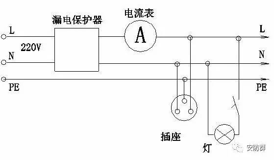
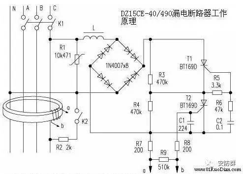
Attached schematic diagram of RCCB/ELCB:
In the figure, L is an electromagnet coil, which can drive the knife switch K1 to disconnect when it leaks, and use two 1N4007s in series for each bridge arm to increase the withstand voltage. The resistance values of R3 and R4 are very large, so when K1 is closed, the current flowing through L is very small, which is not enough to cause K1 to disconnect. R3 and R4 are the voltage equalizing resistors of the SCR T1 and T2, which can reduce the voltage resistance requirements of the SCR. K2 is a test button, which simulates leakage. Press the test button K2, K2 is connected, which is equivalent to the leakage of the external live wire to the ground. In this way, the vector sum of the current through the three-phase power line and the neutral line of the magnetic ring is not zero. There is an induced voltage output at both ends of b, and this voltage immediately triggers T2 to turn on. Because C2 has a certain voltage in advance, after T2 is turned on, C2 is discharged through R6, R5, and T2, so that a voltage is generated on R5 to trigger T1 to turn on. After T1 and T2 are turned on, the current flowing through L increases, which causes the electromagnet to act, and the drive switch K1 is turned off. The function of the test button is to check whether the function of the device is intact at any time. The principle of electromagnet action caused by electric equipment leakage is the same. R1 is a varistor, which plays a role of overvoltage protection.