Mechanism and Features
• The detection element and trip element of the product are set between the input terminal and the output terminal. The operating characteristics of the product cannot be changed by external mechanical devices.
• The operating mechanism has a free tripping function
• The operating components cannot be removed from the outside of the housing. The product housing should not affect the normal operation of the operating mechanism. The component group should replace the contact pressure to ensure that the contact pressure of the product will not change during operation.
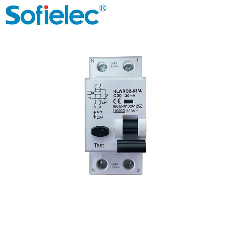
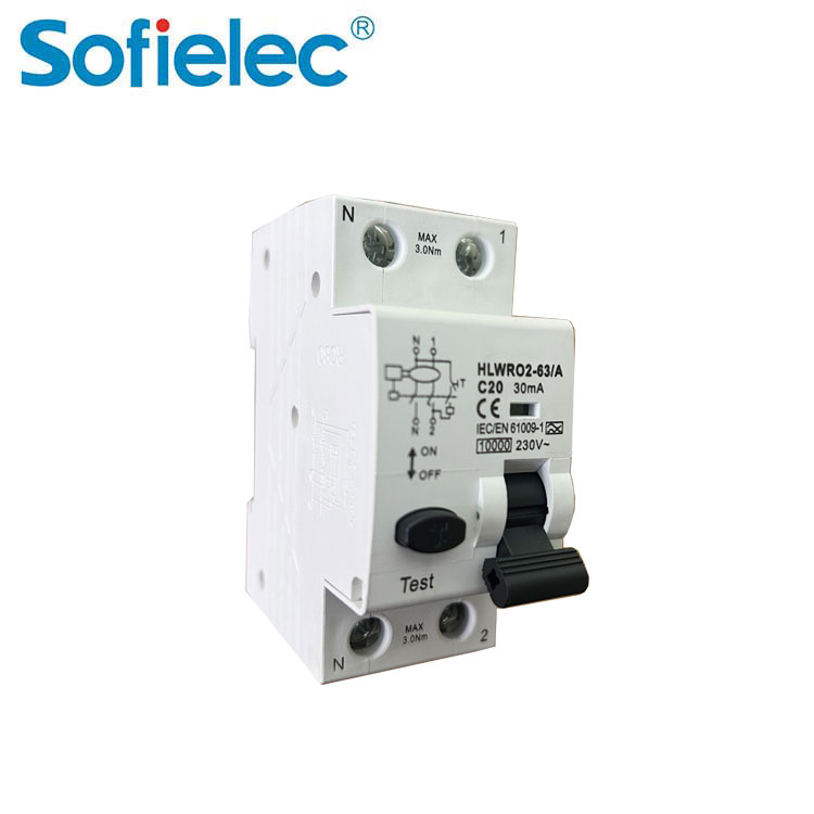
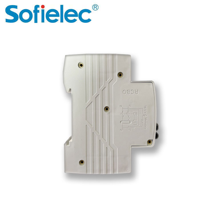
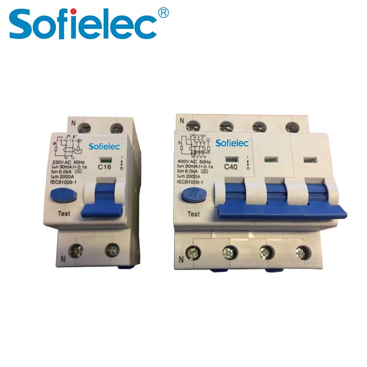
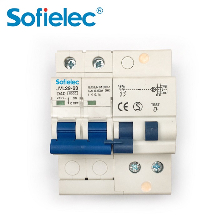
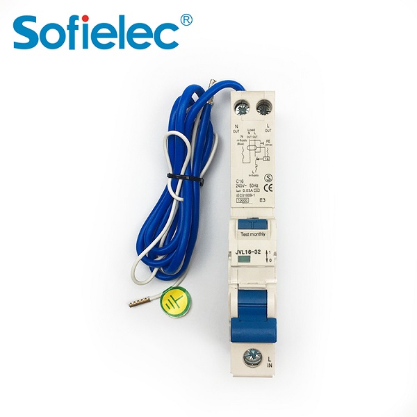
Double breakpoint design of L-pole and N-pole contacts, external heat dissipation groove, with RCBO words and circuit diagram logo, indicator window with glass sheet dustproof, double top rod design of the tripper makes the product tripping mechanism more reliable, 3P+N product handle connection can be directly connected with assembly parts or connected with handle sheath, with wiring module, 1P+N maximum rated current 63A, 1P+N electronic B-type leakage protection performance design…
Technical Parameters
| Product name | Leakage circuit breaker |
| Product model | HLWR02-63 |
| Type | Type A, AC, F, G, S, B |
| Number of poles | 1P+N |
| Rated current | 2、4、6、10、16、20、25、32、40A、50A、63A |
| Rated residual working current l△n(A) | 0.01、0.03、0.1、0.3、0.5 |
| Rated voltage | AC240V |
| Residual working current range | 0.5l△n~△n |
| Working time | ≤0.3s |
| Rated short-circuit breaking capacity | 6000A |
| Mechanical life | Not less than 4000 times |
| Protection level | IP20 |
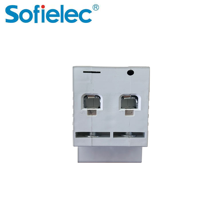
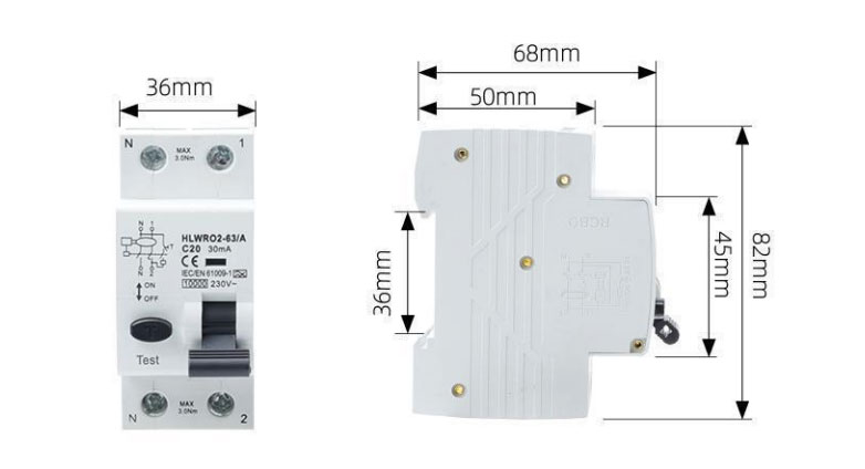
Overall & Installation Dimensions
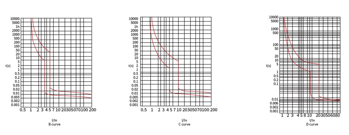
Characteristic curve
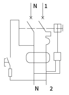
Wiring diagram
Working characteristics
| Testing Procedure | Type | Test current | Initial state | Tripping or non-tripping time limit | Expected result | Notes |
| a | B,C,D | 1.131n | Cold | t≤1h | No tripping | |
| b | B,C,D | 1.451n | Tested | t≤lh | Tripping | Improvement of current stability within 5 seconds |
| c | B,C,D | 2.55ln | Cold | 1s | Tripping | |
| d | B | 3ln | Cold | t≤0.1s | No tripping | Turn on the auxiliary switch to turn off the current |
| C | 5ln | |||||
| D | 10ln | |||||
| e | B | 5ln | Cold | t≤0.1s | Tripping | Turn on the auxiliary switch to turn off the current |
| C | 10ln | |||||
| D | 20ln |
The term "cold" means without any load before testing at the reference set temperature.
Residual current tripping time
| Type | In/A | l△n/A | The residual current (I△) corresponds to the following disconnection time (S) | |||||
| In/A | ln/A | I△n | 2ln | 5l△n | 5A,10A,20A,50A,100A,200A,500A | I△t | ||
| General Type | Any value | Any value | 0.3 | 0.15 | 0.04 | 0.04 | 0.04 | Maximum segment time |
> What Is a Timer Relay?
What’s the difference between on‑delay and off‑delay? Can a timer relay replace a PLC? Answers to 6 common B2B questions.
> Common Causes of Overload Relay Tripping and How to Prevent Them
Why does your motor overload relay keep tripping? Learn real causes (overload, phase loss, ambient heat) and how to prevent false trips.
> Application Guide for Hydraulic Magnetic Circuit Breakers in Sensitive Electronic Equipment
Why use hydraulic magnetic breakers for medical, IT or telecom equipment? Temperature stability, delay curves, and selection tips.
> What Is a Shunt Trip and How Does It Work with MCCB?
Learn what a shunt trip is, how it remotely trips an MCCB, typical voltages, and common applications like emergency stop systems.