English
 Español
How Does a Liquid Level Relay Automate Your Water Pump?
You’re designing a water system—a storage tank that needs filling, a sump pit that needs draining, or an irrigation reservoir that needs level control. The simplest, most reliable solution doesn’t require a PLC or a complex control panel. A liquid level control relay with a few stainless steel electrodes can handle the job automatically. The principle is straightforward: electrodes sense the presence or absence of conductive liquid, and the relay translates that signal into a pump start or stop command. This guide covers the two basic operating modes—fill and drain—along with electrode selection, wiring examples, troubleshooting, and installation best practices. For water system integrators and automation engineers, this is a practical framework for automating pump control with minimal complexity.
Understanding the Two Basic Modes – Fill vs. Drain
A liquid level relay can be configured for two fundamental operations: filling a tank or draining a sump. The difference is simply which electrode triggers the pump start. The same relay hardware supports both modes through simple wiring configuration, allowing you to standardize on one model for multiple applications.
Fill Mode – Keeping a Tank Topped Up
Fill mode is used for water towers, storage tanks, and reservoirs that need to maintain a supply of water. Three electrodes are installed in the tank: a common electrode (longest, always submerged), a low-level electrode (shortest), and a high-level electrode (medium length). When the water level drops below the low-level electrode, the circuit between the common and low electrodes is broken, and the relay energizes the pump to start filling. When the water rises to the high-level electrode, the circuit is completed, and the relay de-energizes the pump to stop.
Drain Mode – Keeping a Sump Empty
Drain mode is used for sump pits, drainage wells, and rainwater collection basins that need to be kept empty. The same three electrodes are used, but the logic is inverted. When the water level rises above the high-level electrode, the relay energizes the pump to start draining. When the water drops below the low-level electrode, the relay de-energizes the pump to stop.
Choosing the Right Electrodes and Cables
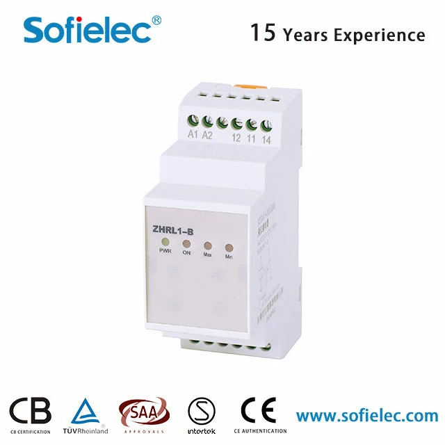
The electrodes are the sensing element of the system. Their material and installation determine whether the relay works reliably. The ZHRL1-B has an adjustable sensitivity range of 5kΩ to 100kΩ, which allows it to work with different liquids and electrode materials.
Electrode Material Selection
For most water applications, stainless steel 316 electrodes are recommended—they resist corrosion in drinking water and wastewater. Copper electrodes work for clean water but are not suitable for acidic liquids. Titanium electrodes are recommended for seawater and highly corrosive environments.
Cable Length and Capacitance Effects
The relay supports cable lengths up to 100 meters. For runs longer than 20 meters, shielded cable is recommended to prevent stray capacitance from causing false triggering. The relay’s adjustable sensitivity helps compensate for cable capacitance in long runs.
Insulation – Only the Tip Should Be Exposed
Only the tip of each electrode should be exposed to the liquid. The rest of the electrode and the cable connection must be insulated to prevent leakage current along the surface of the electrode holder. Use electrode holders made of insulating materials like PP or PTFE.
Wiring Example for Fill Mode (Water Tower)
The wiring is straightforward. Here’s how to connect the relay for a fill application.
Power Connections
Connect the supply voltage to terminals A1 and A2. The relay is available in AC110V, AC220V, and AC380V versions. Ensure the relay’s rated voltage matches your control circuit.
Electrode Connections
Connect three electrodes to the relay: the common electrode (the longest one, always submerged), the low-level electrode (shortest), and the high-level electrode (medium length). The relay measures the resistance between the common electrode and each of the other two to determine the water level.
Output Contacts and Contactor Control
The relay’s output contact (rated at 10A) is connected in series with the contactor coil circuit. When the relay energizes, the contact closes, energizing the contactor and starting the pump. For pumps larger than 1HP, always use a contactor—the relay’s 10A contact is not designed to switch motor loads directly.
Adding a Manual Override
A manual/auto selector switch can be added to the control circuit. In manual mode, the pump runs regardless of the relay‘s state—useful for maintenance or emergency operation.
Troubleshooting Common Issues in Liquid Level Relays
Even a reliable liquid level relay can have problems. Here’s how to diagnose and fix the most common issues.
Pump Doesn’t Start When Water Is Low
If the pump doesn‘t start even though the water level is below the low electrode, check: Are the electrodes covered with sludge or scale? Clean them. Is the cable broken or disconnected? Check continuity. Is the sensitivity setting too low? The relay’s adjustable sensitivity ranges from 5kΩ to 100kΩ—increase the sensitivity if the liquid has low conductivity.
Pump Cycles On and Off Rapidly
Rapid cycling is usually caused by wave action in the tank or electrodes installed too close together. The solution is to increase the delay time. The relay offers a delay range from 0.1s to 10s—set it to 2-3 seconds to prevent the relay from reacting to momentary level changes.
Pump Starts When Electrodes Are Dry
If the pump runs when the tank is empty, there is a leakage path. This is usually caused by: damaged electrode insulation—replace the electrode; moisture on the electrode holder—dry and inspect; sensitivity set too high—reduce it until the false triggering stops.
Installation Best Practices for Long Life
A few simple installation practices will ensure your liquid level relay provides years of reliable service.
Electrode Mounting
Use insulating materials like PP or PTFE for the electrode mounting bracket. This prevents stray currents from traveling along the bracket surface. The electrodes should be spaced at least 50mm apart to prevent short circuits between electrodes.
Regular Maintenance
Clean the electrodes quarterly to remove scale, sludge, or biofilm buildup. The relay is rated IP20, so it should be installed in a clean, dry control cabinet. In cold climates, ensure the electrode cables are frost-protected and the relay is installed indoors.
Document Your Settings
Record the sensitivity setting and delay setting for each installation. When a relay needs replacement, having these settings documented ensures the new unit is configured correctly without trial and error.
| Application | Recommended Electrode Material | Sensitivity Range | Delay Setting |
|---|---|---|---|
| Drinking water / wastewater | SS 316 | 5–50 kΩ | 2–3s |
| Seawater / corrosive | Titanium | 5–20 kΩ | 1–2s |
| Clean water (low conductivity) | SS 316 | 50–100 kΩ | 2–3s |
| Acidic liquids | Titanium | 5–50 kΩ | 2–3s |
What Engineers Ask About Liquid Level Relays
Can I use the same relay for conductive and non-conductive liquids?
For pure water (low conductivity), you need a special high-sensitivity relay (capable of detecting <10µS/cm). The relay has adjustable sensitivity from 5kΩ to 100kΩ, which covers most conductive liquids including tap water, wastewater, and many industrial liquids. For non-conductive liquids (oils, hydrocarbons), a float switch is required.
What is the maximum distance between the relay and electrodes?
The relay supports cable lengths up to 100 meters. For longer distances, cable resistance and capacitance can cause false triggering. Using shielded cable and adjusting the sensitivity can help compensate. For installations over 200 meters, consider a relay with a stronger drive signal.
How do I protect the relay from lightning?
Install a signal surge protective device (SPD) at the point where the electrode cables enter the control panel. The relay is designed for DIN rail mounting in control cabinets, and adding a surge suppressor across the relay input terminals provides additional protection against induced surges.
Can a liquid level relay directly switch a pump without a contactor?
Only for small pumps under 1HP (10A). The relay has a 10A contact capacity, which is sufficient for small pumps. For larger pumps, always use a contactor. The relay‘s contact is designed for control circuits, not for switching motor loads directly.
Ready to Simplify Your Pump Control? Let’s Get the Right Relay
A liquid level relay is one of the simplest, most reliable ways to automate pump control. With the right electrode material, proper wiring, and correct sensitivity settings, you can achieve automatic pump operation without the complexity of a PLC. Contact Sofielec for wiring diagrams and configuration support → —they can provide electrode selection guidance and configuration support for your specific application.
Sofielec manufactures the ZHRL1-B Liquid Level Relay, designed for conductive liquid level control in pump systems. The relay features adjustable sensitivity from 5kΩ to 100kΩ, adjustable delay from 0.1s to 10s, 10A contact capacity, and cable lengths up to 100 meters. Available in AC110V, AC220V, and AC380V versions, it supports both fill and drain modes for water towers, sump pits, and storage tanks. The relay is designed for standard 35mm DIN rail mounting, making it easy to install in new or existing control panels. Sofielec provides technical support including wiring diagrams, electrode selection guidance, and configuration support. Connect with Sofielec to discuss your voltage requirements, electrode material needs, and pump control application.