What Is a Timer Relay?
You’re designing a control panel. You need a component that delays a motor start by five seconds, or keeps a fan running for thirty seconds after a compressor shuts off. You reach for a timer relay—but which one?
A Time Relay is an electrical device that delays the change of its output contact state after receiving an input signal (voltage or contact closure). It has three basic elements: an input signal, a set time, and an output contact. Think of it as a programmable “delay button” that sits between your control signal and your load.
Despite its simple concept, timer relay selection can be tricky. On‑delay vs. off‑delay? Single-function vs. multifunction? Digital vs. analog? This article answers six of the most common questions B2B buyers and users ask about timer relays. By the end, you’ll have a clear framework for selecting the right device for your application.
What exactly does a timer relay do?
Let’s start with the most basic question: what is this device actually doing in your circuit?
The Three Basic Elements
A timer relay has three fundamental components: an input signal (voltage applied or a contact closure), a set time (adjustable via dial or digital display), and an output contact (which changes state after the delay). When the input signal is received, the relay starts timing. When the set time elapses, the output contact switches—from normally open to closed, or from normally closed to open.
A Simple Analogy
Think of it like a “delayed light switch.” You flip the switch (input signal), but instead of the light coming on immediately, it waits for a set number of seconds (delay time), then turns on (output contact changes). The same principle applies to motors, fans, conveyors, and countless other industrial loads.
Common Applications
Timer relays are used for staggered motor starts (preventing inrush current spikes), conveyor delay sequences, fan run‑on after equipment stops, flashing warning lights, and interval timing for cleaning cycles. They’re one of the most versatile components in industrial control.
What’s the difference between on‑delay and off‑delay?
This is the most common point of confusion. The distinction is simple once you understand the trigger.
On‑Delay (Delay on Make)
On‑delay timing starts when power is applied to the relay coil. The output contacts change state only after the set time has elapsed. If power is removed before the time elapses, the timing resets. Typical use: staggering multiple motor starts to reduce inrush current—motor A starts immediately, motor B starts 5 seconds later.
Off‑Delay (Delay on Break)
Off‑delay timing starts when power is removed from the relay coil. The output contacts stay in their energized state for the set time after power is removed, then return to their normal state. Typical use: keeping an exhaust fan running for 30 seconds after a compressor shuts off to clear residual heat or fumes.
Comparison Table
| Feature | On‑Delay | Off‑Delay |
|---|---|---|
| Trigger | Power applied | Power removed |
| Timing Starts | When coil energizes | When coil de‑energizes |
| Output Changes | After set time from power‑on | After set time from power‑off |
| Typical Use | Staggered motor start, conveyor delay | Fan run‑on after compressor stops |
Can a single timer relay do multiple functions?
Yes—that’s the advantage of a multifunction timer relay. It integrates multiple timing modes into one device.
Common Modes
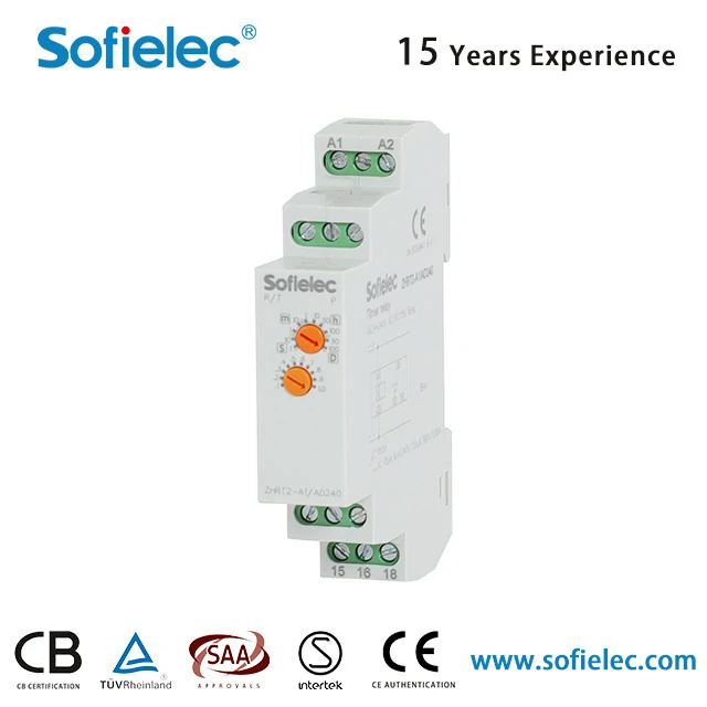
A multifunction timer relay typically includes modes like on‑delay, off‑delay, interval, flashing (pulse), and one‑shot (single pulse). Mode selection is usually via a rotary switch or DIP switches on the device. The ZHRT2‑A1 and other Sofielec models offer broad delay ranges from 0.1 seconds to 100 hours, covering most industrial timing needs.
Pros and Cons
The advantage is clear: one device covers many applications, reducing the number of models you need to stock. For maintenance spares, a multifunction timer is a versatile choice. The drawback: setup is slightly more complex—you need to select the correct mode and set the time correctly. For most users, the benefits outweigh the learning curve.
Recommended Scenario
For equipment maintenance and repair, keep one or two multifunction timer relays in your toolbox. They can replace a variety of single‑function models, reducing downtime when you need a replacement quickly.
How do I wire a timer relay to a contactor?
Wiring is straightforward once you understand the terminal layout. Here’s the typical approach.
Power Supply Connections
Connect the supply voltage to terminals A1 and A2. Common voltages include 24V DC, 110V AC, and 230V AC. The ZHRT2‑A1 supports a wide range: DC12V, DC24V, AC110V, AC220V, AC380V, and AC/DC 24V‑240V. Always confirm the coil voltage matches your control circuit before wiring.
Input Trigger
The input trigger depends on the timing mode. For on‑delay, applying power to A1/A2 starts the timing. For off‑delay, removing power starts the timing. Some models have separate trigger terminals (e.g., Y1‑Y2) for external contact control.
Output Contacts
The output contacts (typically labeled 15‑18 for normally open, 25‑28 for normally closed) connect to the contactor’s coil circuit. When the timer relay’s output changes state, it energizes or de‑energizes the contactor coil, which in turn controls the load.
Critical Warning
Always verify that the contactor coil voltage matches the timer relay’s output contact rating. The relay’s contacts must be rated for the coil’s inrush and holding current. Overloading the contacts will cause premature failure.
Can a timer relay replace a PLC for simple timing tasks?
Yes—for straightforward timing applications, a timer relay is often a more cost‑effective choice than a PLC.
When a Timer Relay Is Sufficient
If your application requires fewer than five timers and the logic is simple (no complex interlocks, math operations, or analog inputs), a timer relay is the right solution. It’s lower cost, requires no programming, and is easier for maintenance staff to troubleshoot.
When a PLC Is Necessary
A PLC is needed when you require math operations, analog input processing, communication with other devices, or a large number of I/O points. Timer relays can’t handle these tasks.
Hybrid Approach
Many systems use a PLC as the main controller, with timer relays as redundant or independent protection devices. For example, a timer relay can provide a backup safety delay that operates independently of the PLC, adding an extra layer of protection.
How accurate are timer relays?
Accuracy depends on the type of timer relay—digital vs. analog.
Digital Timer Relays
Digital (electronic) timer relays with numerical setting offer accuracy of ±0.5% to ±1% of the set value. The ZHRT2‑A1 has a setting accuracy of ≤5% and a repeat accuracy of ≤0.2%. Repeat accuracy—the consistency of timing from one cycle to the next—is often more important than absolute accuracy for most industrial applications.
Analog (Potentiometer) Timer Relays
Analog timer relays with potentiometer adjustment have accuracy of ±5% to ±10%, which can drift with temperature and potentiometer wear. They’re suitable for applications where precise timing isn’t critical.
Recommendation for Industrial Automation
For industrial automation, especially when timing accuracy requirements are below 0.5 seconds, digital timer relays are the preferred choice. They provide consistent, repeatable timing over temperature changes and long service life.
Quick Selection Checklist for Buyers
When selecting a timer relay for your application, consider these five factors:
-
Function – Single function or multifunction? Do you need on‑delay, off‑delay, flashing, or multiple modes?
-
Time Range – What delay range do you need? The ZHRT2‑A1 covers 0.1 seconds to 100 hours, suitable for most applications.
-
Supply Voltage – What voltage is available in your control circuit? Common options: 24V DC, 110V AC, 230V AC.
-
Output Contacts – How many contacts do you need? 1CO (one changeover) or 2CO (two changeovers)? The ZHRT2‑A1 is available in multiple contact configurations.
-
Mounting – DIN rail (35mm) is standard for most industrial control panels.
| Selection Factor | Common Options | ZHRT2‑A1 Capability |
|---|---|---|
| Function | Single / Multifunction | Multifunction (depending on model) |
| Time Range | 0.1s‑100h | 0.1s‑100h |
| Supply Voltage | 24VDC, 110VAC, 230VAC | DC12V, DC24V, AC110V, AC220V, AC380V, AC/DC 24‑240V |
| Output Contacts | 1CO / 2CO | Available in 1C/O and 2C/O configurations |
| Mounting | DIN rail / 8‑pin plug | DIN rail 35mm |
Questions Automation Engineers Ask
Can I use a timer relay for pump control?
Timer relays are designed for fully on or fully off control—not for throttling or variable speed control. They can start or stop a pump after a delay, but they cannot modulate flow. For pump control applications, use a timer relay to sequence pump starts (e.g., delay the second pump start to reduce inrush current) or to provide a run‑on delay after the pump stops.
What is the difference between setting accuracy and repeat accuracy?
Setting accuracy is how close the actual delay time is to the dial setting—for example, if you set 10 seconds, the actual delay might be 9.5 to 10.5 seconds (±5%). Repeat accuracy is how consistent the delay is from one cycle to the next under the same conditions—for example, if the first cycle is 10.2 seconds, the next cycle will also be 10.2 seconds (±0.2%). For most industrial applications, repeat accuracy is more important than absolute setting accuracy.
How do I choose between a timer relay and a PLC for a timing task?
If you need fewer than five timers and no complex logic, math, or communications, a timer relay is usually the more cost‑effective choice. If you need more than five timers, analog inputs, or communication with other devices, a PLC is the better solution. For applications with critical safety timing, consider using both—a PLC for primary control and a timer relay as a redundant backup.
Choosing the Right Timer Relay for Your Application
With a clear understanding of timer relay functions, modes, and selection criteria, you’re ready to make an informed choice.
Sofielec offers a comprehensive range of timer relays designed for industrial automation applications. The ZHRT2‑A1 Time Relay is one of their key models, featuring a wide supply voltage range (DC12V, DC24V, AC110V, AC220V, AC380V, and AC/DC 24V‑240V), a delay range from 0.1 seconds to 100 hours, and repeat accuracy of ≤0.2%. The relay is available with 1C/O (16A) or 2C/O contact configurations and mounts on standard 35mm DIN rail.
Sofielec’s product line also includes multifunction modular timer relays (ATMM series), start‑delta timers (ATMS series), asymmetrical flashers, and on‑delay modular timers, covering a broad spectrum of industrial timing needs. The company is based in Yueqing, Wenzhou, Zhejiang, China, a major hub for electrical component manufacturing.
For control panel builders and OEM equipment manufacturers, having a reliable timer relay supplier is essential. Sofielec’s range allows you to standardize on a few key models while covering most applications—reducing inventory complexity and simplifying maintenance spares.
Whether you need a simple on‑delay for a motor start sequence or a multifunction timer for maintenance spares, the key is understanding your application requirements and matching them to the right device. Start with the selection checklist above, confirm your voltage and time range, and choose a timer relay that meets your accuracy and contact requirements.
Ready to select the right timer relay for your project? Reach out to Sofielec’s team—they can provide technical data sheets, wiring diagrams, and application guidance to help you choose the right model for your control panel.